Section 2.17
DDEC II Electronic Control Module
This system utilizes an engine-mounted ECM only with the EDU components of the DDEC I system contained in the ECM. The replaceable PROM is an EPROM in the DDEC II ECM. The ECM has isolator mounts for both vibration and electrical isolation. Depending upon application, some units have fuel cooling of the ECM. The engine-mounted system simplifies vehicle wiring for greater reliability.
The DDEC II ECM is a microprocessor. It is the control center of the DDEC II system. See Figure "Schematic Diagram of DDEC II" .

Figure 1. Schematic Diagram of DDEC II
The DDEC II ECM is packaged in a die-cast aluminum housing with sealed connectors. See Figure "DDEC III/IV and DDEC II Electronic Control Module (ECM)" . It is mounted on the left side of the engine block.
The DDEC II consists of the following:
- The DDEC II ECM
- A replaceable EPROM
- Connections to various engine sensors, operational displays, power and fuel injectors
Section 2.17.1
Replacement of the DDEC II Electronic Control Module
The DDEC II ECM is a sealed, nonserviceable unit. Tag defective ECM for recore.
Section 2.17.2
Diagnostic Procedures
Basic mechanical checks should be made beforehand to verify that the problem is definitely related to the electrical portion of the system. If the basic mechanical checks fail to locate the problem, refer the Detroit Diesel Single ECM Troubleshooting Manual, (6SE497). Start by reading the "Basic Knowledge Required" section before attempting to diagnosis electrical faults.
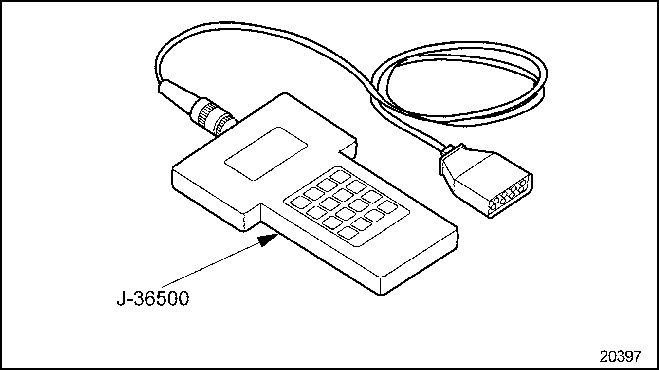
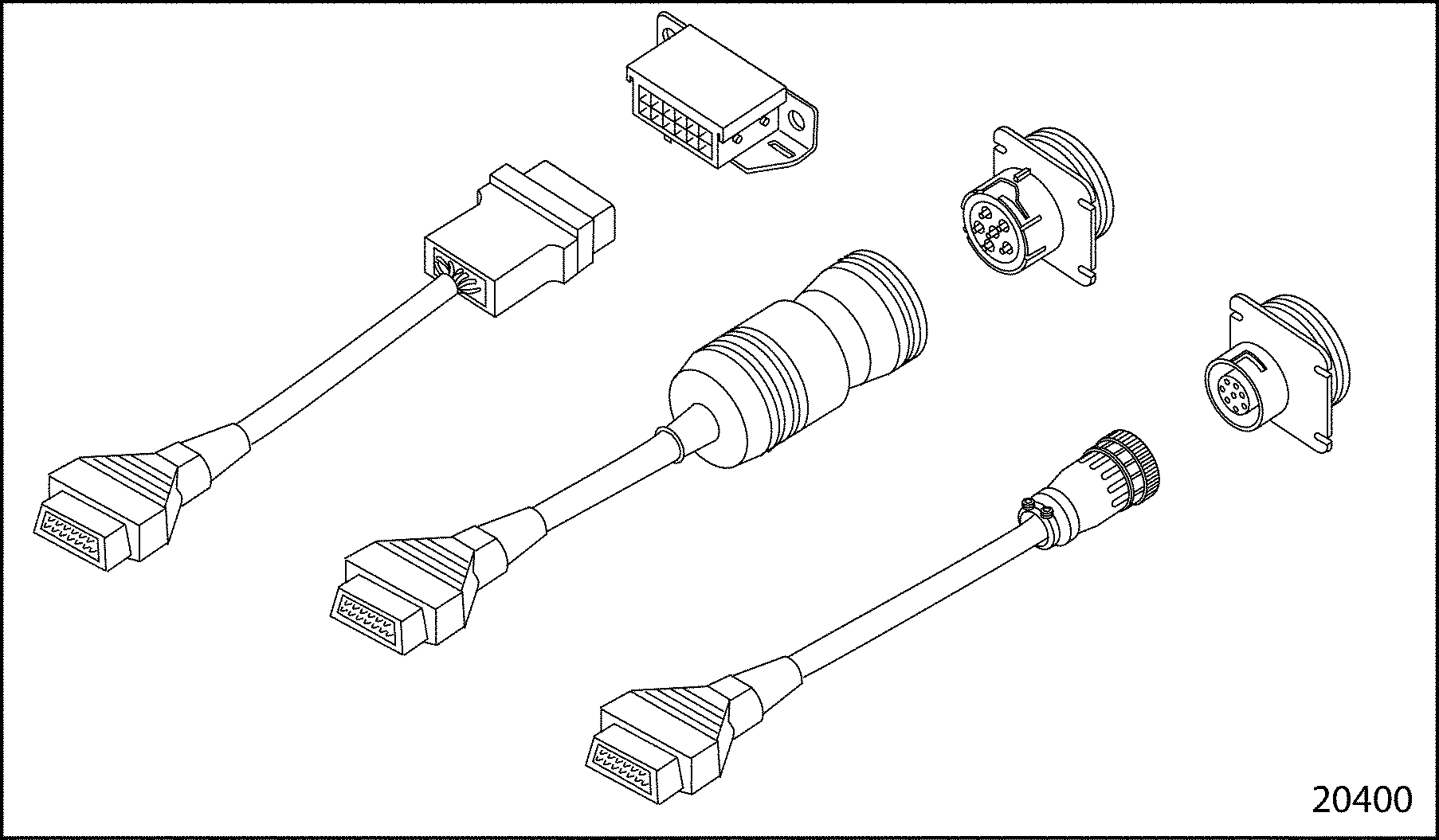
There are two diagnostic Data Readers (DDR) that can be used for diagnosis of DDEC I and DDEC II engines. See Figure "DDEC I & II Reader" and see Figure "DDEC II & III/IV Reader" .

Figure 2. DDEC I & II Reader

Figure 3. DDEC II & III/IV Reader
Section 2.17.3
Removal of DDEC II Electronic Control Module
Perform the following steps for ECM removal:
- Carefully disengage the lock tab on the power harness and injector harness connectors.
- Remove the five (5) wire harness connections at the ECM.
- Remove the through-bolts holding the ECM to the engine.
- Remove the ECM and cold plate from the engine, if so equipped.
- Remove the screws securing the cold plate to the ECM. Remove the cold plate from the ECM, if so equipped.
Section 2.17.4
Installation of DDEC II Electronic Control Module
Perform the following steps for ECM installation:
- Install the cold plate on the ECM, if so equipped. Tighten the screws securing the cold plate to the ECM. Use Loctite® 262, or equivalent, on the cold plate-to-ECM screws. Torque to 9.5-12 N·m (84-106 lb·in.).
- Inspect the ECM isolators for damage and replace if required.
- Mount the ECM and cold plate to the engine.
- Secure the ECM to the engine with through-bolts. Torque the ECM-to-engine bolts to 23-27 N·m (17-20 lb·ft). Torque the ECM connector hold-down screws to 2.4-3.0 N·m (21-26 lb·in.).
- Connect the five (5) wire harness connections at the ECM.
- Engage the lock tab on the power harness and injector harness connectors.
- Turn the ignition to the "ON" position. Observe the DDR for any diagnostic code(s). If any code(s) other than code 25 is logged, refer to the Detroit Diesel Single ECM Troubleshooting Manual
(6SE497).

PERSONAL INJURY
Diesel engine exhaust and some of its constituents are known to the State of California to cause cancer, birth defects, and other reproductive harm.
- Always start and operate an engine in a well ventilated area.
- If operating an engine in an enclosed area, vent the exhaust to the outside.
- Do not modify or tamper with the exhaust system or emission control system.
- Start the engine, and check for fuel leaks.
Using "Check Engine" light, read the DDEC II Diagnostic codes. If the diagnostic reader is not available, the following procedure can be used to read the fault codes using the "Check Engine" light on the dashboard of the vehicle. See Figure "Dashboard Warning Lights" .

Figure 4. Dashboard Warning Lights
If the vehicle is equipped with an OEM supplied diagnostic switch, hold the switch in the "ON" position. This should be done with the ignition on and the engine not running.
If there is no diagnostic switch, locate the 12-pin Diagnostic Data Link (DDL) connector (for DDEC I and II applications only) under the dash of the vehicle. See Figure "Examples of Diagnostic Data Link (DDL) Connector" .

Figure 5. Examples of Diagnostic Data Link (DDL) Connector
NOTICE: |
|
If the vehicle is equipped with an OEM supplied diagnostic switch, the switch must NOT be switched on when operating the vehicle. If this is done, the diagnostic mode line will be grounded, and the throttle will be forced to the idle position, affecting vehicle operation. This condition will not occur when a diagnostic reader is used. |
These methods will cause the Check Engine light to begin flashing a code when the ignition is turned to the ON position. Code 25, for example, would be two flashes followed by a pause, followed by five more flashes. This code would indicate no trouble codes logged since the last system check. This flashing code will be repeated until the diagnostic switch is turned OFF or the jumper wire is removed from pins A and M (on DDEC II engines only). If any code(s) other than code 25 is logged, refer to the Detroit Diesel Single ECM Troubleshooting Manual (6SE497).
Fault codes can be cleared from the DDEC II and III/IV systems only by using a diagnostic reader. Follow the instructions supplied with the reader to clear the fault codes.
Note: Before beginning any repair procedures, the ignition switch must be in the OFF position.
Section 2.17.5
Replacement of the DDEC II EPROM
The following tools are required to replace the former EPROM with the improved EPROM stabilizer kit:
- 1/4 in. Nut Driver
- Thin-head standard screwdriver
- Kent-Moore antistatic wrist strap BT-8639-B (for electrostatic discharge)
To replace a DDEC II EPROM, see Figure "Replacement Flowchart for DDEC II EPROM" .

Figure 6. Replacement Flowchart for DDEC II EPROM
Section 2.17.6
Removal of the DDEC II EPROM
Perform the following steps to remove the former EPROM:
- Using a Diagnostic Data Reader (DDR) (J–38500–B), check for codes in the electronic control module (ECM). Note the codes. Erase the codes.
- Remove the ECM from the engine and take to a clean environment.
NOTICE:
Failure to properly ground your hand while handling the ECM may result in damage to the EPROM, the ECM or both.
- Fasten the wrist strap of tool BT-8639-B securely around your wrist and attach the test clip to a good ground.
- Using the 1/4 in. nut driver, remove the 16 screws which fasten the ECM cover to the case.
NOTICE:
Use care to avoid damaging the cover gasket on the ECM. A damaged cover gasket could allow contaminants to enter the ECM, which may cause damage.
- Using the thin head standard screwdriver, carefully pry the cover loose from the case.
- Early EPROM assemblies may have been installed in a blue 28-pin socket at the end of the ECM and under the stabilizer plate. To remove the EPROM assembly from its socket, push down (unlatch) the blue and white locking tabs and move them to the side. Remove the EPROM. Then, using a suitable narrow diameter tool, remove the locking tabs by carefully pressing out the pins holding the tabs to the socket. Discard the tabs and pins.
Section 2.17.7
Installation of the DDEC II EPROM
Install the improved EPROM stabilizer kit as follows:
- Using the 1/4 in. nut driver, remove the three mounting screws adjacent to the blue 28-pin socket. Discard the screws.
- The EPROM assembly and socket are keyed, so the assembly can be installed only one way. Observe the keying and install the EPROM assembly by pushing it firmly down into the socket.
-
See Figure
"EPROM and Spacer Locations"
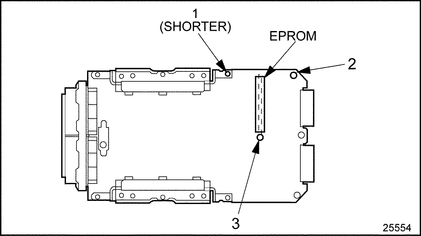
and place the shorter spacer with two bands over the hole at location 1. Place the longer spacers over the holes at locations 2 and 3. Lay the stabilizer plate over the EPROM so that the bolt holes line up with the spacers and the holes in the circuit board. Fasten the stabilizer plate to the case with three #8-32 x 1 3/4 in. screws. Torque screws to 3.0-3.7 N·m (26.6-32.7 lb·in.).

Figure 7. EPROM and Spacer Locations
NOTICE:
Use care to avoid damaging the cover gasket on the ECM. A damaged cover gasket could allow contaminants to enter the ECM, which may cause damage.
- Carefully inspect the cover gasket for any damage or areas where a dust leak could possibly occur.
Note: If the gasket is damaged, it must be replaced with a new gasket.
- Fasten the cover to the case with the 16 previously removed #8 - 32 x 1/2 in. screws. Torque screws to 2.0-2.2 N·m (17.7-19.5 lb·in.).
- Remove the wrist strap and ground clip of tool BT-8639-B and store for next use.
- Test the EPROM for proper installation. Refer to "2.17.7 Installation of the DDEC II EPROM" .
- Install the ECM on the engine. Refer to "2.17.4 Installation of DDEC II Electronic Control Module" .
Section 2.17.7.1
Testing of the ECM
The resistance of the ECM to block must be checked after installation. Use the following procedure:
- With the six-pin connector unplugged, connect the leads of an ohmmeter between the ECM case and the engine.
- Return the removed EPROM assembly to an authorized Detroit Diesel distributor.
| Series 60 Service Manual - 6SE483 |
| Generated on 10-13-2008 |