Section 2.4
N2 Fuel Injector Tube and O-Ring
The bore in the cylinder head for the EUI is directly through the cylinder head water jacket. To prevent coolant from contacting the injector and still maintain maximum cooling of the injector, a copper tube is pressed into the injector bore. The tube has a ring seal at the top and is flared at the bottom, on the lower side of the cylinder head, to create water and gas-tight joints at the top and bottom.
Note: It is recommended that the injector tube be replaced with new parts at the time of engine overhaul.
Section 2.4.1
Repair or Replacement of N2 Fuel Injector Tube
To determine if repair or replacement of the fuel injector tube is necessary. See Figure "Flowchart for Repair or Replacement of N2 Fuel Injector Tube" .
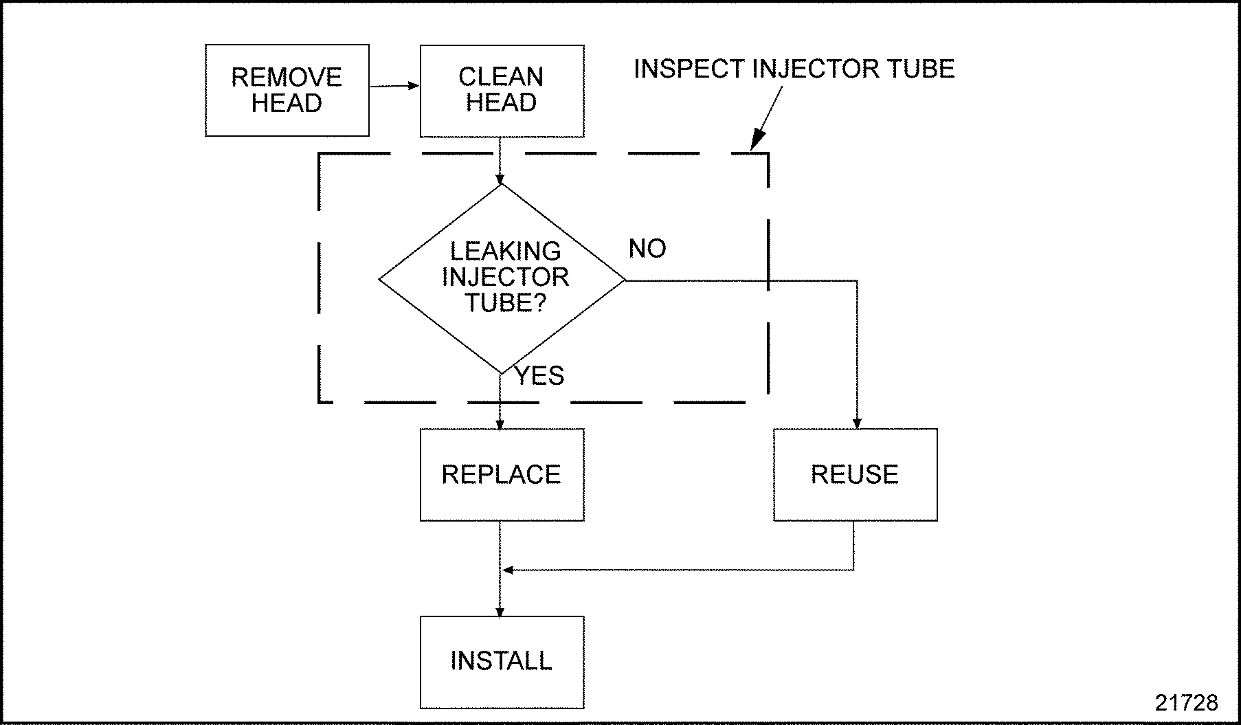
Figure 1. Flowchart for Repair or Replacement of N2 Fuel Injector Tube
Section 2.4.2
Removal of the N2 Injector Tube and O-ring
When removing an injector tube, use J–33880–4 and J–5286–5 (part of tool set J–33880) .
- Remove, disassemble, and clean the cylinder head. Refer to "1.2.2 Removal and Cleaning of Cylinder Head" .
- Place J–33880–4 (part of tool set J–33880)
, in the injector tube. Insert J–5286–5 (part of tool set J–33880)
, through the small opening of the injector tube and thread the pilot into the tapped hole in the end of the installation/removal tool. See Figure
"Removal of N2 Injector Tube"
.
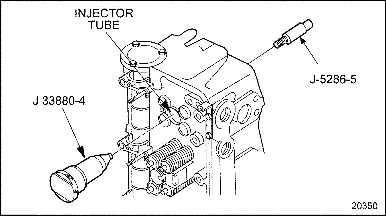
Figure 2. Removal of N2 Injector Tube
- Tap on the end of the pilot using a brass hammer or fiber mallet. Using J–33880–4 and J–5286–5 (part of tool set J–33880) carefully drive and lift the injector tube from the cylinder head. If the injector tube O-ring is not removed with the injector tube, remove the O-ring from the cylinder head casting at the upper end of the injector tube bore. Discard O-ring.
Section 2.4.3
N2 Injector Tube Crevice Volume Removal Tool
Detroit Diesel has made a machining improvement on the Series 60 cylinder head injector tube bore. This machining improvement removes cast iron material from the head at the crevice area, located just above the injector tube to cylinder head sealing land. See Figure "Crevice Area"
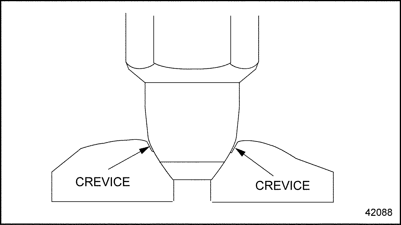
Figure 3. Crevice Area
This process was implemented on new engines beginning with engine serial number 06R0656739. An injector nozzle seat cutter (J–45723) is now available to perform this machining process to engines built before engine serial number 06R656739. This tool includes two replacement bits. Additional bits (J–45723–1, part of tool set J–45723) are also available. See Figure "N2 Injector Nozzle Seat Cutter (J–45723)" .

Figure 4. N2 Injector Nozzle Seat Cutter (J–45723)
This procedure is required whenever the injector tubes are removed and only on engines built before engine serial number 06R0656739.
- Apply cutting oil to cutting bit.
- Ensure injector tubes and O-rings are removed from injector bores.
Note: Do not drop tool in bore, doing so would cause the cutting bit to chip.
- Gently guide the injector nozzle seat cutter (J–45723)
in injector tube bore taking caution not to score injector O-ring sealing surfaces.
Note: Do not rotate tool in the counterclockwise direction as damage to the cutting bit will occur.
- Using a speed handle and socket, turn cutter approximately 10 clockwise rotations at one turn every two seconds using moderate downward force.
- Remove tool and inspect bit after each cut. If bit is chipped remove allan bolt and rotate bit 90 degrees. Replacement bits (J–45723–1, part of tool set J–45723) are available.
- Thoroughly flush metal shavings from injector tube bores.
Section 2.4.4
Cleaning of N2 Injector Tube
Thoroughly clean the injector tube hole in the cylinder head to remove any dirt, burrs, or foreign material that may prevent the new tube from seating at the lower end or sealing at the upper end. Excess material in the form of a small copper ring may be left at the lower end of the injector tube counterbore after the injector tube has been removed. This copper ring will have to be removed using a suitable sharp-pointed tool.
Section 2.4.5
Installation of Auxiliary Injector Seal
Perform the following for installation of auxiliary injector seal.
NOTICE: |
|
If a cylinder head has a damaged injector hole tube seal, coolant may seep past the seal after injector removal. Drain down the injector tube hole, and fill the combustion chamber. If this condition goes undiscovered and the coolant is not removed from the cylinder before the injector is replaced, the engine may be damaged at startup. Always check cylinders for possible coolant seepage before replacing injectors and use care to prevent coolant or fuel from contaminating the engine lubricating oil. |
NOTICE: |
|
Do not use a metal dowel to install the auxiliary injector seal, as this may damage the seal. |
- Place the auxiliary seal in the injector hole.
- Seat it against the top of the injector tube with a 1-5/8 in. diameter wood or plastic dowel. See Figure "Auxiliary Injector Seal Location" .
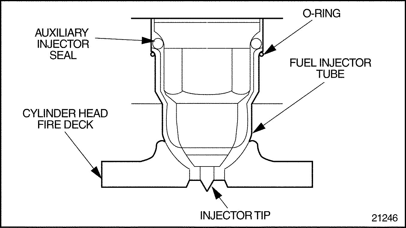
Figure 5. Auxiliary Injector Seal Location
Section 2.4.6
Installation of N2 Injector Tube and O-ring
Perform the following steps for injector tube installation:
NOTICE: |
|
DO NOT lubricate the outside of the injector tube or inside the cylinder head injector tube bore to facilitate installation of the tube. Lubricant may cause the tube to turn during reaming or flaring operations possibly damaging the injector tube or reamers. |
Note: This ring was formerly made of fluoroelastomer and had a blue coating for identification. It is now made of a special blended fluorocarbon material with a green teflon coating for identification. Former and current-design seal rings are completely interchangeable, and only the current green-coated seal ring will be serviced.
- Place the O-ring over the injector tube, sliding it up to the lip. See Figure "Installing O-ring and Injector Tube" .
- Install the injector tube on J–33880–4 (part of tool set J–33880)
. See Figure
"Installing O-ring and Injector Tube"
.
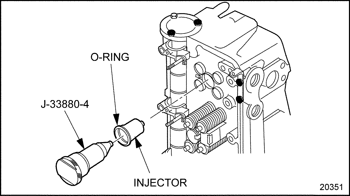
Figure 6. Installing O-ring and Injector Tube
- Install both J–33880–4 (part of tool set J–33880) and injector tube into the injector bore. Ensure the tip of the injector tube goes through the small hole in the fire deck. Tap lightly on the end of the tool, if necessary, to seat the tube.
- Install the EUI hold-down clamp and bolt it in place over J–33880–4
(part of tool set J–33880)
. See Figure
"Installing N2 Injector Hold-down Clamp"
.
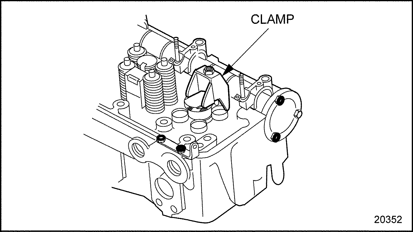
Figure 7. Installing N2 Injector Hold-down Clamp
- Torque the EUI hold-down clamp bolt 58-66 N·m (43-49 lb·ft). This will seat the injector tube at the desired depth.
After an injector tube has been installed in a cylinder head, it must be finished.
Perform the following steps for a flaring injector tube:
- Insert J–5286-6 (part of tool set J–33880) , through the small hole in the bottom of the tube, rotating to engage the threads in the installation/removal tool.
- Using a torque wrench and 12-point, 29/32 in.socket, screw J–5286–6
(part of tool set J–33880)
into J–33880–4 (part of tool set J–33880)
until it begins to flare the tube. See Figure
"Flaring Injector Tube Tip"
.
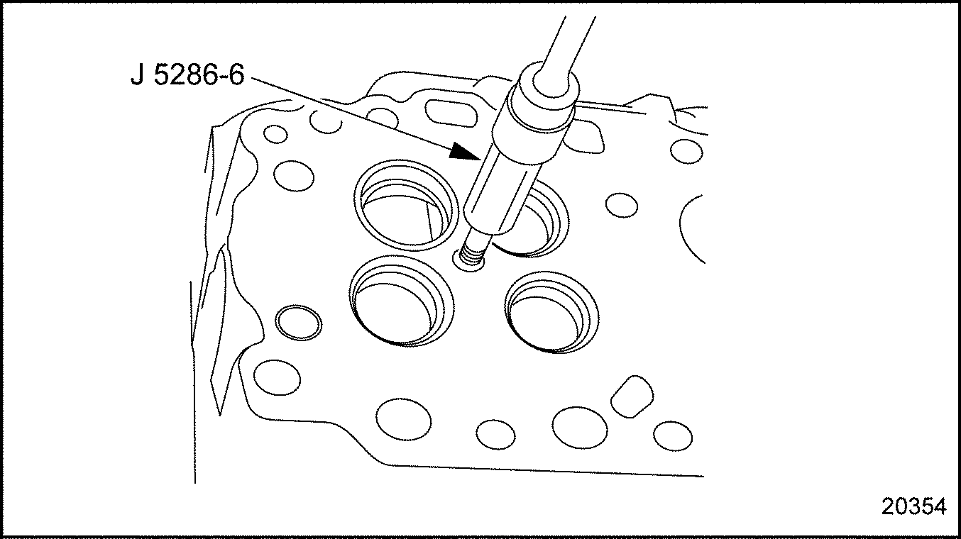
Figure 8. Flaring Injector Tube Tip
- Continue to rotate J–5286–6
(part of tool set J–33880)
and apply pressure to the flare end of the tube firmly against the cylinder head casting tube opening. Do not exceed 41 N·m (30 lb·ft) torque. See Figure
"Properly Flared Injector Tube Tip"
.
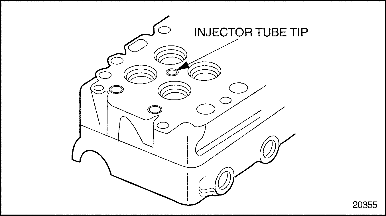
Figure 9. Properly Flared Injector Tube Tip
- Remove J–5286–6
and J–33880
.
The tapered lower end of the injector tube must provide a smooth and true seat for the lower end of the injector nut to effectively seal the cylinder pressures and properly position the injector tip into the combustion chamber. To ream the injector tube, complete the following steps:
- Install J–33880–3 (part of tool set J–33880) , into the injector bore until it contacts the cylinder head. See Figure "Reaming Injector Tube" .
- Install J–33880–10 (part of tool set J–33880)
, into the seat reamer pilot until it bottoms. See Figure
"Reaming Injector Tube"
.
NOTICE:
Turn the reamer in a clockwise direction only (both when inserting and withdrawing the reamer) because movement in the opposite direction will dull the cutting edges of the flutes.
- Place a few drops of cutting oil on the cutting edges of J–33880–5
(part of tool set J–33880)
, and install it in J–33880–10
(part of tool set J–33880)
. See Figure
"Reaming Injector Tube"
.

Figure 10. Reaming Injector Tube
- Using a speed handle with 7/16 in. socket attached, turn the tip reamer in a clockwise direction using light pressure until it goes completely through the end of the injector tube.

EYE INJURY
To avoid injury from flying debris when using compressed air, wear adequate eye protection (face shield or safety goggles) and do not exceed 276 kPa (40 psi) air pressure.
- Remove J–33880–5 (part of tool set J–33880) and J–33880–10 (part of tool set J–33880) . Blow out the injector tube and tip with compressed air to remove all metal shavings.
- Install J–33880–20 (part of tool set J–33880)
, to the firedeck of the cylinder head using two existing head bolts. Tighten the head bolts, but do not torque. Position the cut out portion of the stop block beneath the injector tube. See Figure
"Stop Block Installation"
.

Figure 11. Stop Block Installation
- Install J–33880–3
(part of tool set J–33880)
, into the injector tube bore until it contacts the cylinder head. See Figure
"Reaming Injector Tube Seat"
.
NOTICE:
If the seat reamer is dropped into the pilot, or is allowed to strike the injector, chatter marks may result in the injector tube seat. Use extreme care when inserting the seat reamer to prevent damaging the tube.
- Place a few drops of cutting oil on the edges of J–33880–1 (part of tool set J–33880)
, and gently place it in the pilot. See Figure
"Reaming Injector Tube Seat"
.

Figure 12. Reaming Injector Tube Seat
NOTICE:
Turn the reamer in a clockwise direction only, because movement in the opposite direction will dull the cutting edges of the flutes.
- Using a speed handle with 15/16 in. socket attached, turn the seat reamer in a clockwise direction with light pressure. Continue until J–33880–1 (part of tool set J–33880) bottoms against J–33880–20 (part of tool set J–33880) .
- Inspect the tube seating surface to ensure that there are no irregularities or chatter marks in the seating surface. If irregularities or chatter marks are found, remove and replace the injector tube. See Figure
"Injector Tube Seat Irregularities"
.
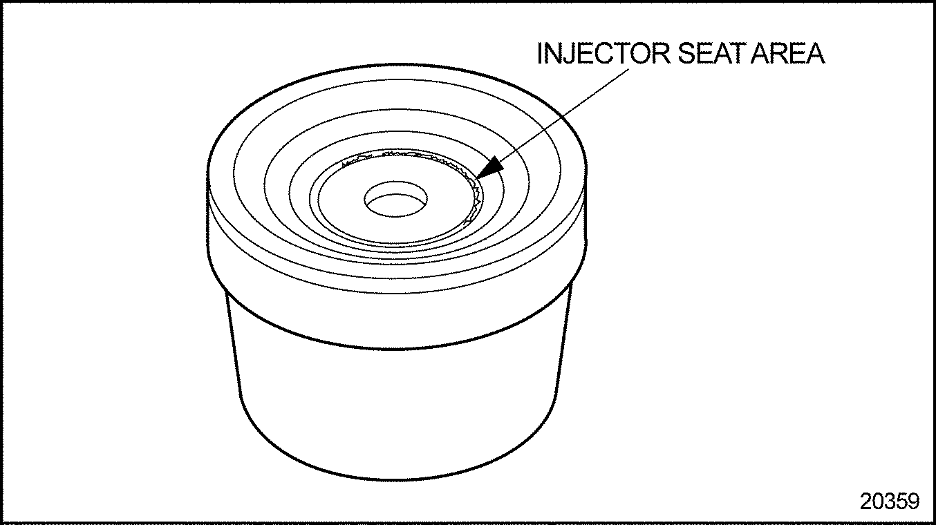
Figure 13. Injector Tube Seat Irregularities

EYE INJURY
To avoid injury from flying debris when using compressed air, wear adequate eye protection (face shield or safety goggles) and do not exceed 276 kPa (40 psi) air pressure.
- Remove the reamer and pilot. Clean out the injector tube with compressed air.
- Remove the two head bolts and J–33880–20 (part of tool set J–33880) from the cylinder head.
- Spot-face the injector tube as follows:
- With the cylinder head firedeck in a workable position, insert the J–5286–8 (part of tool set J–33880) , into the injector tube. See Figure "Refinishing Injector Tube Recess" .
- Using a 12-point socket and speed handle, turn the refinisher to remove excess stock so that the lower end of the injector tube is from flush to -0.20 mm (-0.008 in.) below the firedeck surface of the cylinder head.
- Remove the chips from the injector tube with compressed air. See Figure "Refinishing Injector Tube Recess" .

Figure 14. Refinishing Injector Tube Recess

EYE INJURY
To avoid injury from flying debris when using compressed air, wear adequate eye protection (face shield or safety goggles) and do not exceed 276 kPa (40 psi) air pressure.
Section 2.4.6.1
Check Injector Tip Protrusion
To check the injector tip protrusion:
- Insert J–33880–3 (part of tool set J–33880) , into injector tube bore of cylinder head. See Figure "Reaming Injector Tube" .
- Insert J–33880–7 (part of tool set J–33880)
, into pilot. See Figure
"Checking Injector Tip Protrusion"
.

Figure 15. Checking Injector Tip Protrusion
- Check injector tip protrusion using J–22273–01 . Hold protrusion gage against pilot while measuring tip protrusion. This measurement should be flush to -0.20 mm (-0.008 in.).
| Series 60 Service Manual - 6SE483 |
| Generated on 10-13-2008 |