Section 1.29
Camshaft Drive Gear
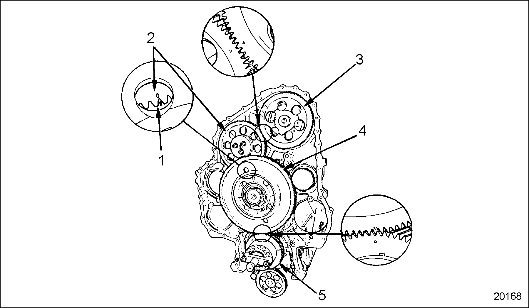
The camshaft drive gear, located at the front of the engine, under the gear case cover, is driven by the crankshaft through a series of intermediate gears. See Figure "Engine Gear Train and Timing Marks" .

|
1. Idler Gear, Camshaft |
4. Bull Gear |
|
2. Idler Gear, Adjustable |
5. Timing Gear, Crankshaft |
|
3. Drive Gear, Camshaft |
Figure 1. Engine Gear Train and Timing Marks
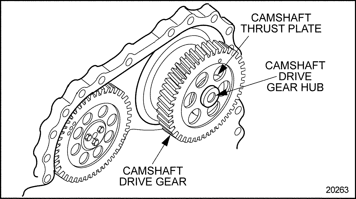
The gear train for the crankshaft drive consists of a crankshaft timing gear, mounted to the end of the crankshaft, meshing with a bull gear. To the rear of the bull gear is the camshaft idler gear, which is mounted on the same hub and rotates at the same speed as the bull gear. The camshaft idler gear meshes with an adjustable idler gear, which is mounted on a separate hub. The adjustable idler gear in turn meshes with the camshaft drive gear, which is mounted on the camshaft drive gear hub. The gears are designed so that the camshaft is driven at half crankshaft speed.
Since the camshaft must be timed exactly to the crankshaft, a series of timing marks are stamped or etched on the gear faces of these gears so that they may be installed in correct relationship to each other.
The camshaft drive gear is keyed and pressed onto a hub located in the thrust plate assembly at the end of the camshaft. The camshaft drive gear and hub are retained to the end of the camshaft by the camshaft drive gear retaining bolt which goes through the camshaft drive gear and the hub, and is threaded into the end of the camshaft. See Figure "Camshaft Drive Gear and Related Parts" .

|
1. Bolt, Thrust Plate Retaining (2) or (3) |
6. Gear Case |
|
2. Bolt, Camshaft Hub Retaining |
7. Seal, Thrust Plate |
|
3. Drive Gear, Camshaft |
8. Camshaft |
|
4. Thrust Plate, Camshaft |
9. Key |
|
5. O-ring |
10. Hub |
Figure 2. Camshaft Drive Gear and Related Parts
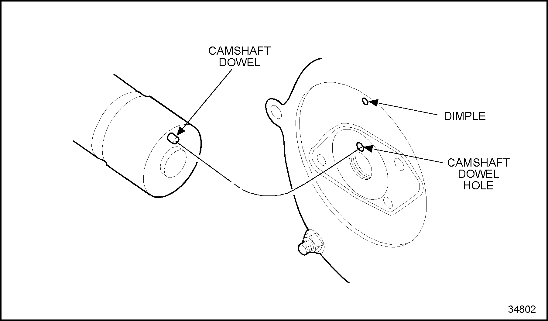
The camshaft is indexed to the hub by a dowel. The camshaft drive gear hub rides in a camshaft thrust plate, which is retained by two bolts. One of these bolts screws into the cylinder head, while the other bolt screws into the No. 1 camshaft bearing cap.
The camshaft thrust plate is sealed to the gear case by an O-ring which fits into a groove machined in the outer diameter of the thrust plate, which is retained by three (current) or two (former) bolts. One of these bolts screws into the cylinder head, while the other bolt screws into the No. 1 camshaft bearing cap. A diamond shaped rubber seal that fits into a groove machined in the rear camshaft thrust plate face, seals the camshaft thrust plate to the cylinder head and No. 1 camshaft cap. The dimple in the thrust plate must be installed at the 12 o'clock position to allow alignment of the thrust plate bolt holes with those in the cylinder head and No. 1 camshaft cap. See Figure "Camshaft Thrust Plate and Dowel Pin Location" .

Figure 3. Camshaft Thrust Plate and Dowel Pin Location
The camshaft thrust plate can be moved horizontally in the gear case, to allow camshaft and cylinder head removal without damaging the thrust plate seal or removing the gear case cover. The camshaft drive gear will stay in mesh with its mating gear, and may be returned to its original position without re-timing the gears.
Section 1.29.1
Repair or Replacement of Camshaft Drive Gear
To determine if repair or replacement of the camshaft drive gear is necessary, preform the following procedure. See Figure "Flowchart for Repair or Replacement of Camshaft Drive Gear" .

Figure 4. Flowchart for Repair or Replacement of Camshaft Drive Gear
Section 1.29.2
Removal of Camshaft Drive Gear
Remove the camshaft drive gear as follows:
- Remove the engine valve rocker cover. Refer to "1.6.2 Removal and Cleaning of One-piece Rocker Cover For Diesel Engines Only" for one-piece rocker cover. Refer to "1.6.3 Removal and Cleaning of Two-piece Rocker Cover For Diesel Engines Only" for two-piece rocker cover. Refer to "1.6.5 Removal and Cleaning of Three-piece Rocker Cover" for three-piece rocker cover.
- Remove the camshaft drive gear access cover, fan bracket, (refer to "4.6.3 Disassembly of Engine Cooling Fan"
) and camshaft retaining bolt, refer to "1.28.2 Removal of Camshaft and Camshaft Bearing"
.
NOTICE:
Use care when removing the camshaft thrust plate retaining bolts to prevent their accidental dropping into the gear case and causing engine damage.
- Working through the access holes in the camshaft drive gear, remove the three (current) or two (former) bolts that retain the camshaft thrust plate to the cylinder head and No. 1 camshaft bearing cap. See Figure
"Camshaft Thrust Plate Mounting Bolt Locations"
.

1. Camshaft Thrust Plate Mounting Bolt Locations
Figure 5. Camshaft Thrust Plate Mounting Bolt Locations
- Pull the cam gear thrust plate assembly forward as far as possible to separate the assembly from the camshaft using J–35906 .
- Remove the gear case cover. Refer to "1.10.2 Removal of Engine Gear Case Cover" .
- Using a fiber mallet or plastic hammer, tap the rear face of the camshaft thrust plate forward until it is free of the gear case.
- Remove the camshaft thrust plate, hub, and camshaft drive gear as an assembly. See Figure
"Camshaft Thrust Plate Assembly"
.

Figure 6. Camshaft Thrust Plate Assembly
- Support the camshaft drive gear, with thrust plate facing down, on blocks.
- Press the hub out of the camshaft drive gear until the hub separates from the camshaft thrust plate. See Figure
"Camshaft Hub Removal"
.

Figure 7. Camshaft Hub Removal
- Remove the O-ring and seal from grooves in the camshaft thrust plate. Discard O-ring and seal.
- Using a hooked seal extractor, remove the diamond seal from the thrust plate groove.
Section 1.29.2.1
Inspection of Camshaft Drive Gear
Inspect camshaft drive gear as follows:
- Clean all parts with fuel oil.

EYE INJURY
To avoid injury from flying debris when using compressed air, wear adequate eye protection (face shield or safety goggles) and do not exceed 276 kPa (40 psi) air pressure.
- Dry them with compressed air.
- Examine the camshaft drive gear teeth for scoring, pitting, excessive wear and cracking, peening of the Woodruff Key slot. If damage is found, replace as required.
- Visually examine the camshaft drive gear hub for scoring, pitting, galling or cracking. If damaged, replace drive gear hub.
Section 1.29.3
Installation of Camshaft Drive Gear
Install the camshaft drive gear, hub and thrust plate as follows:
- Coat the contact surfaces of the hub and camshaft thrust plate with clean engine oil. See Figure
"Cross-Section of Camshaft Drive and Related Parts"
.

1. Woodruff Key
5. Groove, Seal
2. Hub, Camshaft Drive Gear
6. Dowel Hole, Camshaft
3. Drive Gear, Camshaft
7. Thrust Plate, Camshaft
4. Groove, O-ring
Figure 8. Cross-Section of Camshaft Drive and Related Parts
- Install the hub to the camshaft thrust plate.
- Install the key into the keyway on the hub.
- Apply a thin film of Lubriplate to the bore of the camshaft gear.
- Support the hub from the engine side.
NOTICE:
A minimum force of 20 kN (4500 lb) must be obtained when pressing the gear on the hub which can distort camshaft gear if applied off center. Only apply force to the inner hub of the gear when pressing.
- Align the keyway in the camshaft drive gear with the key in the hub and press the gear, onto the hub until it is firmly seated against the shoulder.
Section 1.29.3.1
Testing of Camshaft Drive Gear Assembly Run-out
Measure the camshaft drive gear assembly run-out as follows:
- While supporting the camshaft thrust plate on blocks, position the camshaft drive gear assembly with the engine side facing down.
- Assemble a dial indicator and magnetic base with the indicator stem resting on the face of the camshaft drive gear, just inboard of the drive gear teeth. Zero the dial indicator.
- Rotate the drive gear two full rotations while reading the total indicated run-out.
Note: The total amount the dial indicator needle moves to the left and right of zero, added together, gives the total indicated run-out Total Indicator Reading (TIR).
- If the measured value is 0.114 mm (0.0045 in.) or less, then the drive gear assembly can be reused.
- If the measured value is more than 0.114 mm (0.0045 in.), the drive gear assembly parts must be replaced.
Section 1.29.4
Installation of Camshaft Drive Gear
Continue installing camshaft drive gear assembly as follows:
- Coat the camshaft thrust plate O-ring with clean engine oil.
- Install it into its groove in the camshaft thrust plate.
- Install a new diamond seal in the camshaft thrust plate groove by pressing it in with the rounded end of the seal extractor or the flat end of a ruler.
- Be sure the O-ring sealing surface of the gear case is clean and free of burrs.
- Install the hub and camshaft thrust plate to the opening in the gear case. The depression in the rear face of the camshaft thrust plate must be positioned at 12 o'clock, see Figure "Camshaft Thrust Plate and Dowel Pin Location" , to align the retaining bolts in the thrust plate with those in the head and No. 1 camshaft cap.
- Using a fiber mallet or plastic hammer, tap the camshaft drive gear at 90 degree intervals toward the engine, until the thrust plate bolts can be started in the cylinder head and No. 1 camshaft cap.
NOTICE:
Make sure camshaft dowel hole in camshaft drive hub is aligned with camshaft dowel prior to tightening thrust plate bolts. A misaligned hub can cause damage to the camshaft and thrust plate components
NOTICE:
Use care when installing the camshaft thrust plate retaining bolts to prevent accidentally dropping them into the gear case and causing damage to gear train.
- Using a 13 mm socket and ratchet, tighten the thrust plate bolts alternately and evenly to draw the thrust plate straight into the gear case. Torque the bolts to 30 - 38 N·m (22-28 lb·ft).
- Install the gear case cover. Refer to "1.10.3 Installation of Gear Case Cover"
.
NOTICE:
Always hold the camshaft drive gear stationary using camshaft drive gear retaining tool (J–35652–B) to prevent component damage, while loosening or tightening the camshaft drive gear-to-camshaft bolt.
Note: Before installing the fan support bracket and camshaft drive gear access cover, it will be necessary to install and tighten the camshaft drive gear retaining bolt, and to measure and adjust the adjustable gear-to-camshaft drive gear lash.
- Install retaining tool(J–35652–B)
and tighten the camshaft drive gear retaining bolt as follows:
NOTICE:
Failure to tighten the camshaft hub retaining bolt to the required torque may result in bolt loosening during engine operation, which may lead to camshaft alignment pin damage, altered engine timing, and erratic engine operation.
- Apply a small amount of International Compound #2®, or equivalent, to the bolt threads and underside of the bolt head.
- Install the bolt through the hub and thread into the camshaft.
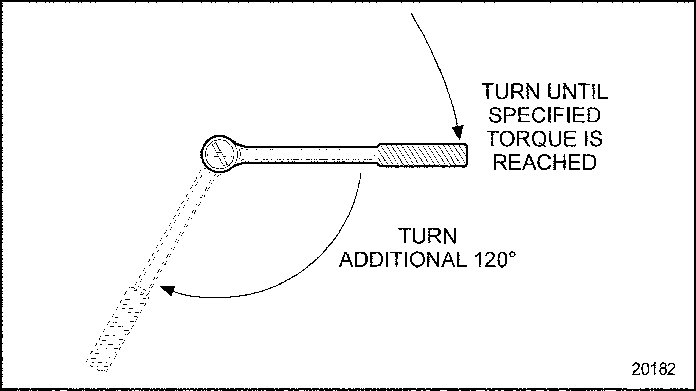
- Torque bolt to 75 N·m (55 lb·ft).
- Turn the bolt an additional 120 degrees. See Figure "Torque Turn Limits" .

Figure 9. Torque Turn Limits
- Check the gear train timing and adjustable idler gear-to-camshaft drive gear lash. Refer to "1.24.2.1 Check Engine Timing" .
- Install the camshaft drive gear access cover. Refer to "1.10.3 Installation of Gear Case Cover" .
- Install the fan bracket. Refer to "4.6.6 Installation of the Engine Cooling Fan" .
- Install any components that were removed for access to the gear case cover.
- Check the lubricating oil. Refer to "14.6.1 Lubricating Oil" .
- Check the coolant level. Refer to "14.6.4 Cooling System" .
- Refer to "12.7 Engine Run-in Instructions" for verification of proper camshaft drive gear installation.
| Series 60 Service Manual - 6SE483 |
| Generated on 10-13-2008 |